
Friction dampers
Below the platform between neighbouring blades. Normal load, friction coefficient and contact stiffness decide how far the resonance drops.
*SURFACE INTERACTIONApplications
Wherever components touch, stick, slip or lift off, the dynamics become nonlinear. We compute them with OrAgL in the frequency and the time domain and evaluate them in ARGUS: in turbomachinery, gearboxes and bolted joints.
01 · Turbomachinery
The most important application of OrAgL: bladed structures in aero engines, gas and steam turbines and compressors. Contacts at the platform, shroud and blade root damp vibration and shift resonances. How reliably they do so decides design and service life.
Below the platform between neighbouring blades. Normal load, friction coefficient and contact stiffness decide how far the resonance drops.
*SURFACE INTERACTIONContacts at the blade tip couple the wheel. Gap, preload and creep change their behaviour over the service life.
Dovetail and fir-tree joints: micro-slip in the interface adds damping and stiffness that depend on the amplitude.
Self-excited vibration that only friction limits: limit cycles with aerodynamic coupling.
*LCO · *AEROCOUPLINGA friction damper only works within a window of normal load. Too low, and it slips almost freely. Too high, and it sticks and stops damping. In between lies the tuning with the lowest resonance amplitude. OrAgL traces these responses across the frequency range and varies the parameters systematically.
Schematic, not solver output: harmonic balance of a blade as a single-degree-of-freedom oscillator with frictional contact.
With cyclic symmetry, OrAgL computes a single sector and assembles the wheel through nodal diameters. ARGUS shows the computed mode shapes as an animation on the FE model, as a sector or as the full wheel, and makes the contact state at the interfaces visible.
*CYCLIC SYMMETRY MODEL*MISTUNING*ANIMATE SYSTEM*ANIMATE INTERFACE
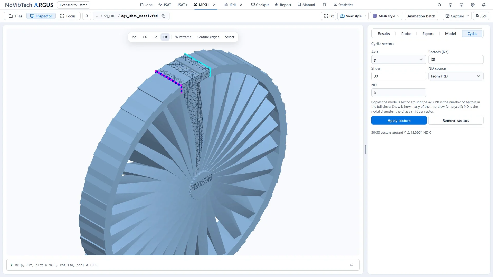
ARGUS MESH: a sector model, expanded through cyclic symmetry to a wheel with 30 sectors.
02 · Gearboxes
In the gear mesh, the contact is preloaded. Once the vibration exceeds the static deflection, the teeth lift off and strike again. The stiffness drops, the resonance bends towards lower frequencies, and during run-up and run-down the response jumps between different branches.
Loss of contact and re-contact in the model, with contact stiffness or as a rigid contact.
Which branch the system follows depends on its history. Continuation reveals every branch, frequency sweeps in the time domain show the actual path.
*CONTINUATION CONTROLS*FSWEEP
Transient simulation with rigid contact when impacts and their consequences are the focus.
*NOSTIA
Mechanical Systems and Signal Processing
03 · Bolted joints
Bolted structures are usually analysed as linear, yet behave nonlinearly: even at small amplitudes the interface starts to slip at its edges. The natural frequency drops and the damping rises. Often the joint is the most important source of damping in the whole assembly.
Amplitude-dependent behaviour from the contact model of the joint interface, instead of blanket damping assumptions.
How bolt load and interface design shift frequency and damping, systematically across variants.
Model reduction and substructuring for thin-walled, frictionally clamped structures.
*ROM*SUBSTRUCTURE ROM
Mechanical Systems and Signal Processing
Mechanical Systems and Signal Processing
Methods
Both views belong together. Harmonic balance delivers periodic responses quickly and with every branch. Time integration shows transients, sweeps and impacts as they actually unfold.
Periodic and quasi-periodic responses, continuation across the frequency range including unstable branches, nonlinear modal analysis.
*HBM · *FRF · *NMA · *CONTINUATION CONTROLSTransient responses to periodic excitation and frequency sweeps, limit cycles and tori, impacts at rigid contacts. Stored states serve as starting points for continued runs.
*NOSTIA · *HARMONIC · *FSWEEP · *MWF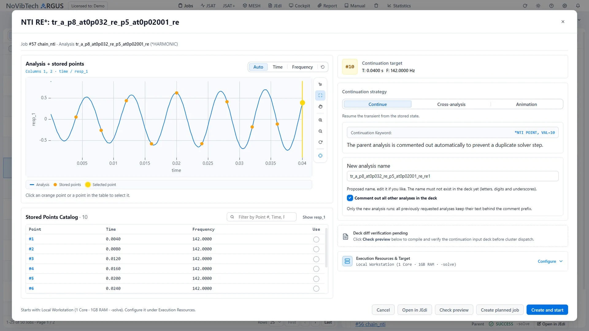
*HARMONIC). Stored states are starting points for a continued run or an animation.Next step
Contact and friction are part of many assemblies. Describe your structure briefly and we will tell you what can be computed.
 ARGUS · MESH